Airfoil Thickness Calculator
Calculate airfoil thickness ratio (t/c) from maximum thickness and chord, or solve for any variable. Get the nearest NACA thickness code, a profile plot, and a comparison with real airfoils.
https://hexacalculator.com/calculators/physics/mechanics/airfoil-thickness-calculator
Physics
Mechanics
Airfoil Thickness Calculator
Calculate airfoil thickness ratio (t/c) from maximum thickness and chord, or solve for any variable. Get the nearest NACA thickness code, a profile plot, and a comparison with real airfoils.
Airfoil Thickness Calculator
%
Enter any two of maximum thickness, chord length, and thickness ratio, and the calculator fills in the third.
Please input values into the fields
Was this calculator helpful?
It takes one click and shapes what we fix next.
Add as preferred on GoogleShow the airfoil profile
Draw the symmetric airfoil shape for your thickness ratio.
Show how your airfoil compares
Plot your thickness ratio against a range of real airfoils.
The aspect ratio, which is the maximum thickness divided by the length of a wing, is one of several numbers that aircraft designers specify at the outset. It determines how much room there is inside the wing for spars and fuel, as well as having a major effect on drag and stall behavior.
If you input the maximum thickness and chord length of any airfoil profile, you will get the aspect ratio. Conversely, you can also enter an aspect ratio and one of the lengths to calculate the other length. This is a ratio that can be derived from NACA airfoil numbers and is also used to compare different airfoils.
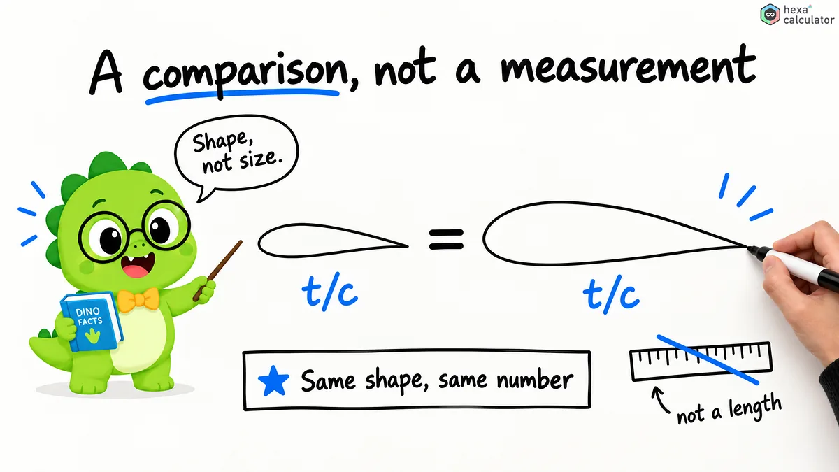
What is meant by wing strength?
A wing profile is the cross-sectional shape of a wing, propeller or blade. The chord length is the straight-line distance from leading edge to trailing edge. The maximum thickness is the greatest distance between top and bottom surfaces, measured perpendicular to the chord line.
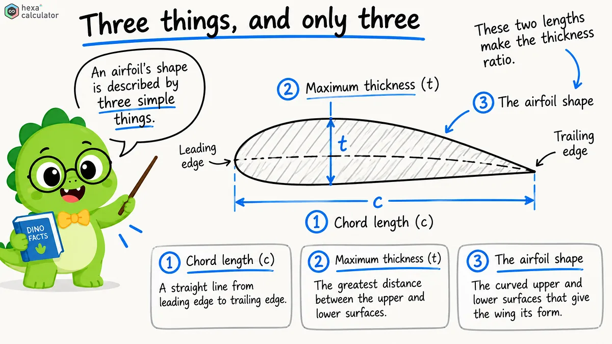
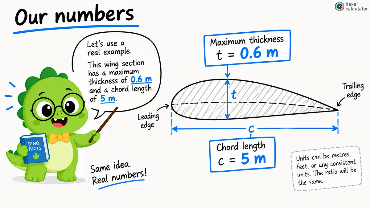
The aspect ratio is abbreviated t/c and indicates the percentage of the maximum thickness in relation to the length of the wing. For a wing with a length of 5 meters and a maximum thickness of 0.6 meters, the aspect ratio is 12 percent. This single value indicates the depth in relation to the length of the airfoil profile, and many design decisions are based on it.
Here's how to use this calculator.
Enter any two of the three values and the program will calculate the remaining value. Each length input field has a separate units menu so you can easily mix different units like meters, centimeters, millimeters, inches, and feet. The resulting thickness is always shown as a percentage though.
Assume the wing length is 3 meters and the target for thickness ratio is 12 percent. If you leave the maximum thickness blank, the program will calculate a value of 0.36 meters. Conversely, if you measure the existing wing length and maximum thickness, you can immediately get the thickness ratio. The airfoil profile shown below is drawn based on the entered thickness ratio.
Formula for calculating thickness ratio:
The calculation is done by a division that then converts to a percentage.
In this formula, 't' is the maximum thickness and 'c' is the length of the blade. Since both values must have the same units, the ratio itself has no units. By rearranging the formula, you can either calculate the length or the maximum thickness.

Example calculation:
Let's take the example of a Boeing 737. For a wing rib with a wing depth of about 5 meters and an almost supercritical wing profile with a thickness ratio of nearly 12 percent,
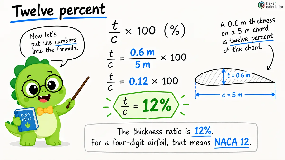
the maximum thickness is as follows:
This means that the internal depth is about 60 centimeters which is enough to fit fuel and landing gear.
Let's look at the F-16. The wing depth is about 2 meters, and the thickness ratio is about 4 percent.
The internal depth is only 8 centimeters. This wing is essentially a high speed and low drag airfoil with the compromise being an extremely small interior volume, thus this aircraft must use external fuel tanks.
How to read a NACA airfoil number:
The thickness ratio can be derived from the four-digit NACA airfoil designation. The last two digits of the number give the thickness ratio as a percentage so that the thickness ratio for NACA 2412 is 12 percent and that of a symmetrical airfoil, NACA 0006, is 6 percent. This calculator will show the nearest NACA thickness code next to the given thickness ratio. For example, if the result is 12 percent, then the code 12 will be shown while a single digit value like 6 percent will be represented as the full number 06.
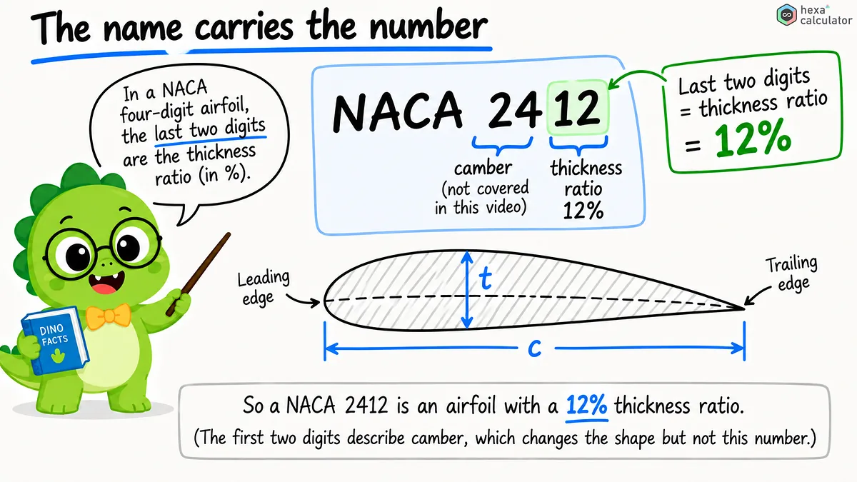
The first two digits of the number indicate the curvature, i.e. the curved shape of the wing, and have no effect on the thickness ratio. Symmetrical wings do not have any curvature, and the form shown in the cross-section is exactly that.
Common values for thickness to string ratio:
Real airfoils have a wide range of thickness-to-chord ratios and the appropriate value depends on the flight speed of the wing and the loads encountered. The following table gives you a rough idea of different design areas.
Application | Typical t/c | Why |
|---|---|---|
Supersonic fighter | 3 to 5% | Low wave drag above the speed of sound |
Airliner wing | 10 to 14% | Efficient cruise with room for structure and fuel |
Light aircraft | 12 to 15% | Gentle stall and easy handling at low speed |
Sailplane | 13 to 18% | High lift for slow, efficient soaring |
Wind-turbine root | 25 to 40% | Maximum strength where bending loads peak |
Thin versus thick wing profiles:
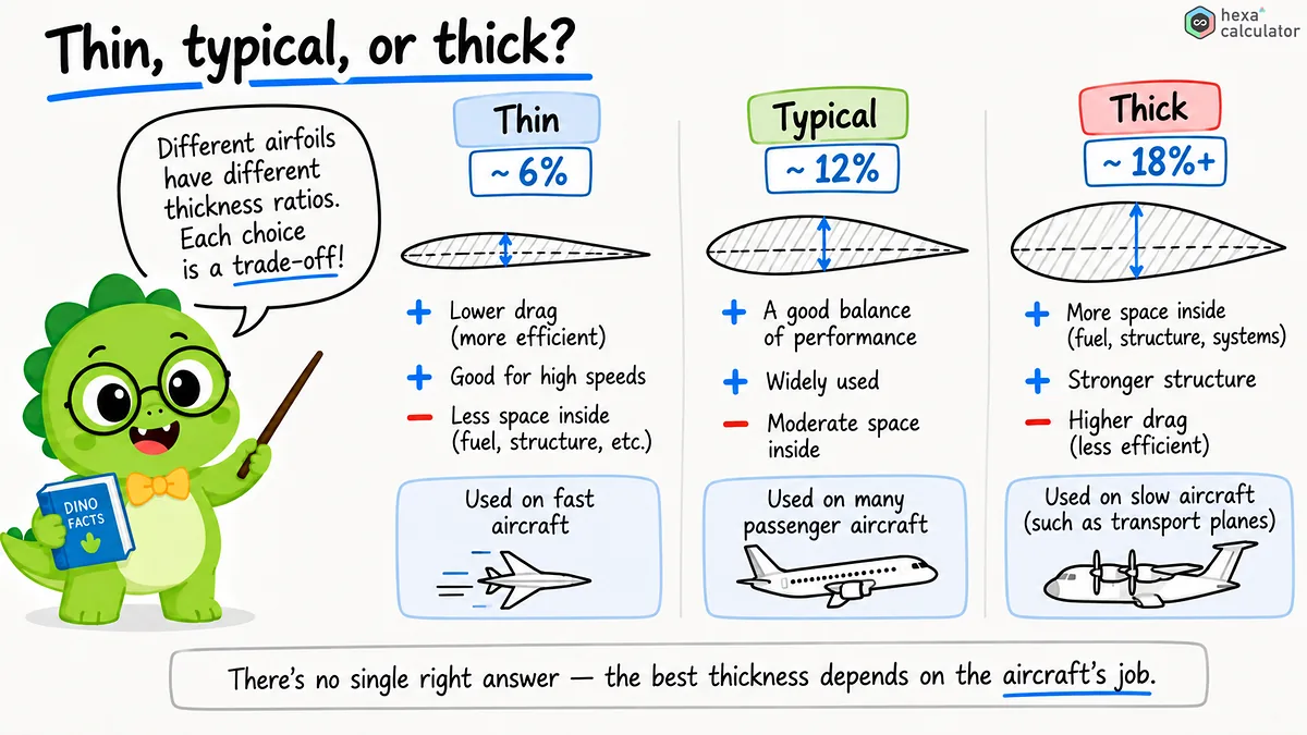
Thicker airfoils (roughly more than 15 percent) can maintain higher lift at lower speeds, have a gentler stall behavior and offer enough depth for robust yet lightweight spars. The disadvantage is that drag increases rapidly as the flow speed approaches the speed of sound.
Thinner airfoils (roughly less than 8 percent) can maintain lower wave drag at transonic and supersonic speeds. This is why high-speed jets often use thin airfoils. As a compromise, they have less internal volume, more abrupt stall behavior, and are less tolerant. Most everyday-use wings fall in the range of 8 to 15 percent, which represents a compromise between the two.
Areas of application
Setting the thickness-to-chord ratio at the beginning of design simultaneously determines fuel volume, structural weight and aerodynamic properties. A thicker airfoil can carry bending loads with lighter materials while a thinner airfoil requires stronger materials to perform the same function because of its reduced depth.
Wind turbine blades follow the same principle; the root is thicker to provide strength, tapering towards the tip for efficiency. Aircraft and marine propellers behave similarly, showing this pattern of change along the transition from hub to blade tip.
Tips for accurate results:
If you're calculating the aspect ratio by hand, use the same units for both measurements of length. Mixing meters and feet will lead to incorrect results without your realizing it. This tool does the conversion for you, so you can enter thickness in centimeters and wingspan in feet.
As a true airfoil profile becomes progressively thinner along the span, the thickness-to-length ratio will change from the root to the tip of the wing. When stating the thickness-to-length ratio always state at what position along the span it was measured.
Frequently asked questions
What is a typical ratio of wing depth to width?
Most transport aircraft use a thickness-to-chord ratio of about 10 to 14 percent, while light aircraft usually have values around 12 to 15 percent. The airfoils of supersonic fighter jets are much thinner and have a ratio of about 3 to 5 percent. Wind turbine rotor blades can reach ratios up to 30 to 40 percent at the root in order to maintain strength.
How to derive thickness from a NACA airfoil designation?
For a four-digit NACA airfoil, the last two digits indicate the thickness of the airfoil as a percentage. The thickness-to-chord ratio of the NACA 2412 is 12 percent while that of the NACA 0006 is 6 percent. The first two digits indicate the camber, not the thickness.
Can the value for the ratio of wing depth to width be greater than 100 percent?
This is not possible with flying objects. A value that exceeds 100 percent would mean that the thickness of the wing profile is longer than its length. The actual values vary from about 3 percent for supersonic fighter jets to around 40 percent at the root of wind turbine rotor blades.
The greater the ratio of thickness to span, the higher the air resistance?
Not necessarily at low speeds. Moderate thickness airfoils can have a lower overall drag than very thin airfoils because they can generate lift more efficiently. The negative effects of the thickness on drag become significant only at transonic and supersonic speeds, because shock waves play an important role at that point.
What is the effect of thickness to span ratio on flow separation?
Thicker airfoils tend to break away gradually and often warn the pilot with vibrations before lift is lost. Very thin airfoils can suddenly break away without warning, which requires more careful control at high angles of attack.
Related calculators






Disclaimer: This calculator is provided for general informational and educational purposes only. Our calculators are under active development, and results may be inaccurate, incomplete, or unsuitable for your situation. Always verify the figures independently and seek advice from a qualified professional before relying on them. We make no warranties and accept no liability for any loss or decision arising from use of this tool.
References
- Wikipedia: NACA airfoil
How the NACA four-digit thickness and camber designation works, with the thickness distribution equation this calculator's profile chart uses.
- Wikipedia: Chord (aeronautics)
Definition of the chord line and how thickness and camber are measured against it.
- AeroToolbox: NACA 4 Series Airfoil Generator
Interactive generator that plots NACA four-digit airfoils from camber, camber position, thickness, and chord.