Anti-Dive Calculator
Calculate anti-dive percentage from suspension link angle, braking force distance, and CG height. Solve for any value, plot the tuning curve, and see what the result means for braking feel.
https://hexacalculator.com/calculators/physics/mechanics/anti-dive-calculator
Physics
Mechanics
Anti-Dive Calculator
Calculate anti-dive percentage from suspension link angle, braking force distance, and CG height. Solve for any value, plot the tuning curve, and see what the result means for braking feel.
Anti-Dive Calculator
%
Enter the suspension link angle, the braking force distance, and the CG height, and the anti-dive percentage appears here. To work backward, type the percentage you want and leave one geometry field blank instead.
Please input values into the fields
Was this calculator helpful?
It takes one click and shapes what we fix next.
Add as preferred on GoogleShow how anti-dive changes with link angle
Sweeps the link angle and plots the anti-dive percentage for your distance and CG height.
Show the angle reference table
Anti-dive at a set of standard link angles, for your braking force distance and CG height.
When the brake pedal is depressed, the front of the vehicle dips down. This is called dive and it happens because deceleration shifts weight to the front wheels and compresses the springs in the front suspension. Anti-dive geometry counteracts this tendency by arranging the steering arms at an angle so that braking force itself creates a pull-up force on the frame, resisting its tendency to dip forward.
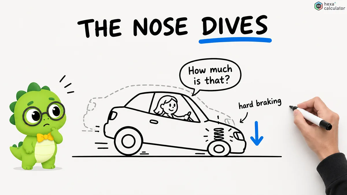
This calculator calculates how much the geometry induced weight transfer to the front is reduced. By entering the angles of the suspension arms, the lever arm length and the center of gravity position, the anti dive value can be found out. Conversely, by entering a target value and leaving one input field for the geometry blank, the required parameters can also be calculated.
What is anti-dive?
Anti-dive is a property of the geometry of the front suspension and has nothing to do with brakes or springs. When braking, weight shifts forward and tries to rotate the front end of the vehicle down. How much the vehicle actually dives depends on how the suspension arms are oriented as seen from the side of the vehicle.
If the wishbones are arranged so that their extension lines in a side view lie behind the center of gravity of the vehicle, part of the braking load is not absorbed by the springs but transmitted directly as a pull force upwards to the vehicle frame. This upward-pulling force is the anti-dive effect. The resulting value indicates what percentage of the lowering is prevented by the geometry.
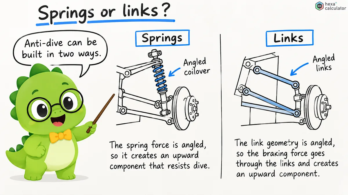
Zero percent means that the geometry has no effect and all weight movements are absorbed by the springs. One hundred percent means that the links absorb all the weight movement and completely prevent the springs from compressing when braking. Most road vehicles fall between these two values.
Instructions for using the calculator:
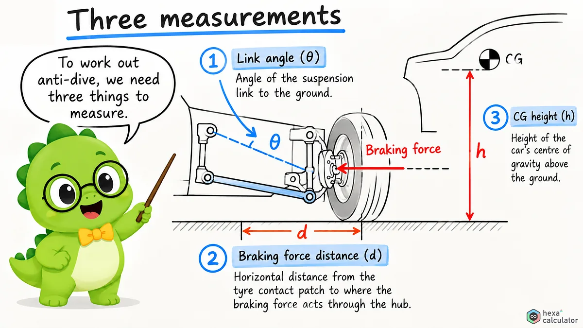
You can fill in any three of the four input fields and the calculator will automatically calculate the fourth field. Normally you would enter the connection angle, brake force effective distance, and center of gravity position to determine the anti-dive value. Each input field has a units menu so that you can mix metric and imperial units or switch between degrees and radians.
To adjust a design to a target value, enter the desired anti-dive value and leave one of the geometry fields blank. If you leave a field blank for which you want a calculation, the tool will output that value (angle, distance or CG position).
Anti-dive calculation equation:
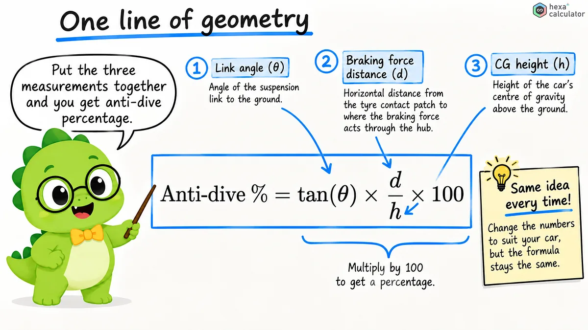
This value is determined by a simple relationship between three measured values.
The Greek letter theta represents the angle of the connection, d is the effective distance of the braking force and h is the center of gravity position. The tangent of this angle corresponds to the inclination of the wishbone. When you multiply this inclination by the effective distance of the braking force, you get the upward force generated by the geometry. By dividing this force by the center of gravity position, a measure for the vehicle's tendency to tilt forward when braking is obtained.
Let's take a real vehicle as an example. The center of gravity is 500mm, the steering wheel angle is 10 degrees and the effective distance of braking force is 300mm.
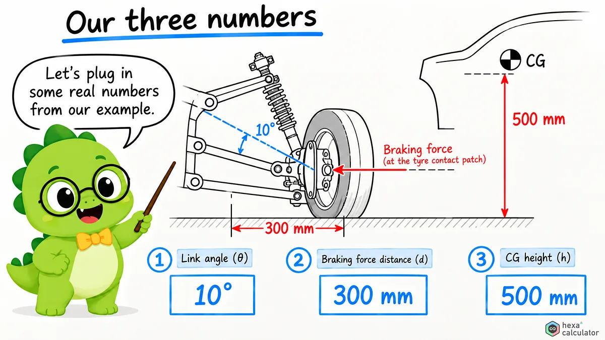
The tangent of 10 degrees is approximately 0.1763. Multiply this by a distance of 300mm, divide it by a height of 500mm and finally multiply it by 100.
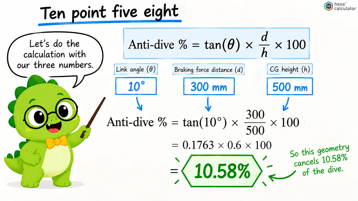
This geometry compensates for about 10.6 percent of the weight transfer on braking. The units cancel out because the distances and heights are in a ratio. If both values were measured in the same unit (e.g., inches) then the result would be the same.
What the percentage means:
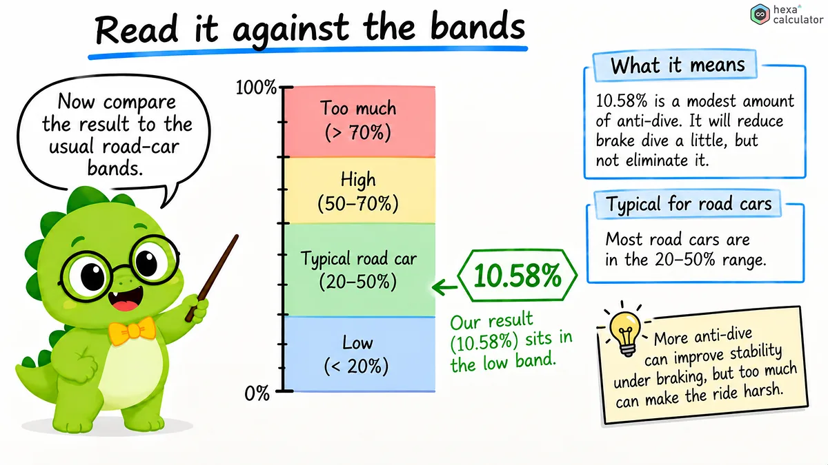
There is no one "correct" number for the anti-dive setting; there is only a suitable range which depends on the vehicle and its intended use. The following table gives rough guidelines as to what characteristics are typically found within each range.
Anti-dive | How it tends to behave |
|---|---|
0 percent | No geometric resistance; the springs absorb all of the dive |
15 to 50 percent | Typical road-car range; a settled nose with usable feedback |
50 to 100 percent | Aggressive and race-oriented; very firm, little dive cue, can feel harsh |
100 percent or more | Jacking: the front lifts instead of diving, often with wheel hop |
Production vehicles are usually between 15 and 50 percent. Racing cars tend to use higher values. In downforce vehicles it is even possible for the geometry at rest to be set to a value in excess of 100 percent, to ensure that it will be correct at high speeds and when the suspension compresses due to aerodynamic pressure. Off-road vehicles usually have lower values to allow sufficient travel over rough terrain.
What affects anti-dive setting:
Anti-dive systems not only stabilise the front of the vehicle. They prevent the front wheels from hitting the shock absorber stops when braking, thus maintaining contact with the road and keeping the camber constant. This means that even in critical situations, the tyres on the front have optimum grip. In vehicles with a low ground clearance, anti-dive systems also protect the underbody and other components, which would otherwise be too low.
The disadvantage is reduced feedback. As the driver normally gauges braking force by the lowering of the front end of the vehicle, this cue is lost with full anti-dive and only the load feel through the seat remains. Many engineers therefore set a value of about 80 percent as a practical upper limit to control the body enough without completely removing feedback. The position of the anti-dive system also affects dive rate, bump-steer characteristics, and scrub radius, so changes in geometry are always more comprehensive than just one number.
Anti-Dive, Anti-Lift and Anti-Squat
Anti-dive is one element of a series of geometric effects. Anti-squat counteracts the tendency for the rear end to dip under high acceleration, and is thus the counterpart to anti-dive. On front- or all-wheel drive vehicles, anti-lift ensures that the front end maintains contact with the road surface when power is applied. This is particularly common on rally cars, which need good traction at the front wheels coming out of a corner. All three systems work in the same way: they transfer some of the load shift via connecting rods rather than directly through springs.
Brake force distribution and wheel travel
The values shown here refer to the geometrically induced anti-dive effect integrated into the connecting rods. The actual braking performance also depends on how the braking forces are distributed between front and rear axle. As only the forces acting on the front wheels pass through, a higher brake force distribution on the rear axle leads to a slightly lower perceived anti-dive effect. Also spring stiffness is important: At equal anti-dive rate, a vehicle with softer springs will drop more than one with harder springs. Since the angle of the connecting rods changes with the spring travel, the calculated anti-dive values at stationary body deviate during the spring travel. Therefore race teams check these values not only in one position but over the entire spring travel.
Three input values are measured.
Begin with the suspension links' angles. Project the pivot point position of the control arm onto a side view of the vehicle and measure the angle between the line connecting two points and the ground. Use an inclinometer in the vehicle and CAD software to measure on the drawing. The brake track is the horizontal distance from the tire contact patch to the braking force line in a side view passing through the suspension pivot point.
The center of gravity is the easiest value to estimate but it forms the basis for all calculations and should be carefully measured. A common method is to place the vehicle on a four wheel scale, lift one end by a known amount, then read off how the weight has been distributed. From this change the center of gravity can be determined. Measure using actual specifications used and include fuel in the vehicle, driver, and any additional weights.
Frequently asked questions
What is a suitable anti-dive value?
Most production vehicles use values between 15 and 50 percent. This allows the rear of the vehicle to be stable when braking while still maintaining comfort and feedback from the brakes. Racing cars tend to use higher values, whereas off-road vehicles generally use lower values in order to protect suspension travel.
Is it possible that there is an anti-dive value too high?
There is a point where if the load exceeds 100 percent, the front end of the vehicle does not squat when braking but rather lifts up. This lift effect usually comes with wheel hop and reduces the weight on the contact patch of the front tires. Even at near 100 percent loading, the suspension will barely give any feedback as to squats which many drivers do not like.
Does anti-dive affect driving feel?
Indirectly yes. A high anti-dive value means that more braking load is transferred through the body and not over the springs, which can cause the vehicle to feel harsher when going over bumps. Also, the driver lacks the usual cue of the front end of the car sinking in. A combination of a low anti-dive value and soft springs can lead to a lot of dive, making the car feel unstable. Comfortable tuning requires a balance between geometry, spring rate, and damping.
How do you measure the angle of the suspension arms?
The pivot point position of the upper wishbone is projected onto a side view of the vehicle and the angle between a line connecting two points and the horizontal plane of the ground measured. A digital inclinometer can be used on the vehicle itself. CAD software may also be used to construct the geometry.
What is the difference between anti-dive and anti-squat?
Anti-dive resists the nose of a vehicle from sinking during braking, while anti-squat resists the tail of a vehicle from sinking during acceleration. Both concepts are based on the same geometric idea but applied to opposite ends of the suspension and under different loading conditions. Anti-dive and anti-squat both transfer load shift through links instead of springs.
Related calculators





Disclaimer: This calculator is provided for general informational and educational purposes only. Our calculators are under active development, and results may be inaccurate, incomplete, or unsuitable for your situation. Always verify the figures independently and seek advice from a qualified professional before relying on them. We make no warranties and accept no liability for any loss or decision arising from use of this tool.
References
- Wikipedia: Anti-dive and anti-squat suspension geometry
Definitions and geometry of anti-dive and anti-squat.
- Wikipedia: Weight transfer
How braking and acceleration shift load between the axles.
- Wikipedia: Car suspension
Overview of suspension types and the geometry terms used here.